Ad Hoc Topics
Up until now we have managed to tell the well control story as a kind of narrative where many topics segue into one another. There are a bunch of smaller topics that need to be covered to ensure we have delivered the full IWCF syllabus, and they have been collected together into this chapter. As before please give your instructor your full attention during this session – these notes are purely for review and do not replace the classroom delivery session.
Top hole
Top hole can be defined as any hole section that is drilled before the BOP stack is installed for use shutting in the well and therefore shallow gas is any gas accumulation encountered while drilling top hole. Shallow gas is often normally pressured – but can be abnormally pressured. Due to the small margin between formation pressure and fracture pressure there is little room for error while drilling top hole so there will be approved procedures in place for drilling this section.
If returns are being taken to the rig while drilling top hole (land rig, platform, jack up sometimes) then certain drilling practices can be put in place. A pilot hole can be drilled to minimise the rate of kick taken should you encounter shallow gas and drilling a pilot hole also allows you to increase APL very quickly should a kick occur thereby also minimising the rate at which it comes into the well.
Drilling rates should be controlled to minimise the build-up of cuttings with regular viscous pills pumped to help with hole cleaning. Usually a pit of kill mud should be mixed and ready at all times. Diverter drills should be held regularly therefore wind direction should be known and monitored by the driller. Pumping out the hole will help eliminate the likelihood of swabbing and a non-ported float will be run in the drill string.
If a shallow gas kick is taken while drilling then keep pumping and activate the diverter which will be sequenced to open the overboard line then close the flow line then close the diverter. Pumps should be increased to maximum speed and then lined up on the pit of kill mud and rig personnel mustered with a view to abandoning the rig.
If a shallow gas kick is taken and you are drilling riserless from a floater then the pumps should be increased to maximum speed and lined up on the kill mud. A rig/well specific plan should then be implemented which may include such things as dropping the string and moving off location or continue pumping as long as is safe and hope the well bridges over.
Horizontal well control
The basic well control principles in horizontal wells are the same as they are for a vertical well - TVD is still used to work out hydrostatic pressure, BHCP and kill mud density. The kick warning signs and indicators are the same as in a vertical well as should be the first actions to take – close the well in following your company approved shut in procedure.
Due to the potential for a long exposed reservoir to go underbalance the influx flow rates and subsequent kick sizes can be greater than in a vertical well. SIDPP and SICP will be equal if a kick is taken regardless of pit gain. Gas is likely to sit on the high side of the well in the horizontal section but will not migrate along the horizontal section.
The Wait & Weight Method gives no benefit to the pressure at the casing shoe during a horizontal kill and often no benefit to surface pressures so the Driller’s Method is favoured because circulation can commence as soon as pressures have stabilised. Initial pump speeds may have to be higher than ‘normal’ to generate enough turbulent flow in the annulus to ‘scoop’ out any gas that is lying in pockets in the high side of the well.
When calculating the pressure step down as kill mud is pumped using a standard vertical kill sheet may result in pressures being much higher than required. A horizontal kill sheet with distinct reductions for each section of the well should be used. As with a vertical kill the pressure should fall by itself as the U-tube balances out.
Wire line operations
Due to the small diameter of the tools, wire line operations have a minimal swabbing and surging effect on BHP - large bore tools could however, so displacement values for the tools and the wire line being used need to be known and carefully monitored while running and pulling wire line.
If wire line operations are being conducted through the drill string then a fully opening safety valve should be installed, and cutters should be on the drill floor. If the well flows the tools should be pulled off bottom (to ensure the line drops clear of the safety valve) and the wire line cut under tension. The safety valve should then be closed followed by the approved shut in method.
If wire line operations are being conducted with special pressure control equipment then the equipment must be compatible with the wire line in use, be capable of forming a seal around the cable and shearing the cable and be pressure rated and tested using applied surface pressure.
If wire line operations are being conducted without any special pressure control equipment then drilling fluid will be the primary means of well control with the rig BOP as the secondary. Company procedures will dictate how the well is to be secured in the event of a kick during wire line operations.
It may be that the annular is closed and an attempt made to strip the wire line and tools out through the BOP. It may not be possible to maintain a seal on the wire line while attempting this. Surface stack you could cut the wire line at the rig floor and then close the blind/shear rams.
Casing operations
Kicks could occur while running casing through losses caused by excess surge pressures when running casing into the well or loss in hydrostatic pressure caused by casing float failure if casing is not kept full when running casing into the well. Kicks could occur while pulling casing due to swabbing when pulling casing from the well.
A self-filling float system can be used when running casing as it reduces surge pressures allowing casing to be run more quickly. It also makes trip monitoring calculations easier – why? Problems can be encountered if the self-filling float fails to convert as cement will tend to u-tube back into the casing if a back pressure is not maintained. If it fails to convert and a kick is taken then the influx could enter the casing string.
If the well kicks during casing operations then it should be secured immediately either using specific casing rams, if installed, or by closing the annular preventer. Closing pressures may need to be adjusted depending on casing OD, collapse pressure and BOP to be used. A circulating head (swage) should be available and checked it fits before running casing.
Cementing operations
Bottom hole pressure can increase during cementing operations due to APL caused by cement pump rate and because of the increase in hydrostatic from the density of spacer and cement entering the annulus. It can decrease due to density of cement reducing as cement sets.
There are many factors that can influence how successful a cement job will be including ensuring combined hydrostatic pressure of mud, spacer and cement slurry in the annulus will not exceed fracture pressure; cleaning mud off the inside of the casing before circulating cement slurry; ensuring filter cake and mud are cleaned off the side of the well bore before circulating cement slurry into place and making sure casing is centralised in the well.
Other factors include calculating accurate volumes of spacer and slurry; calculating strokes required to bump plugs; minimising the cement set time once it has been circulated into position in the annulus; moving the casing string during cement displacement to prevent settling; understanding the signs of cement going into “free-fall” and have a plan as to how to react correctly.
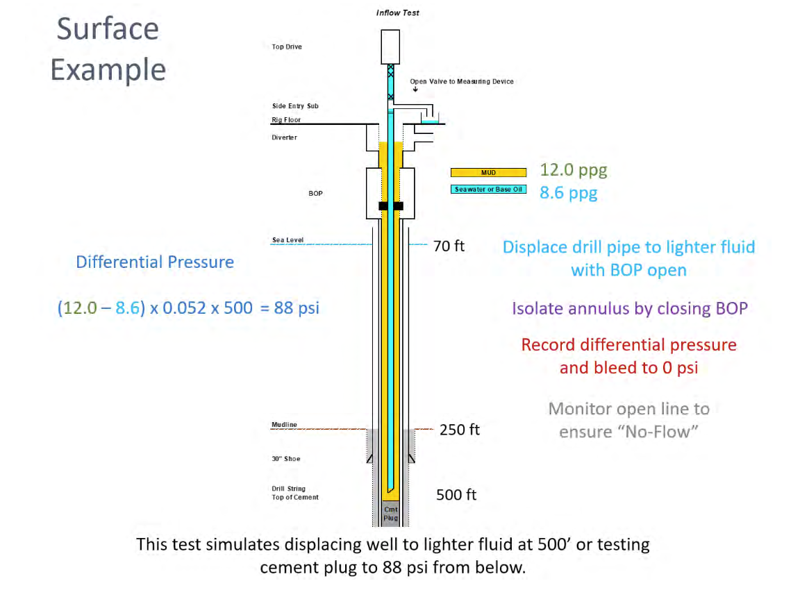
Inflow testing
An inflow test (or negative test) is defined as a test where the hydrostatic pressure is reduced so the net differential pressure direction is from the formation into the wellbore. Inflow testing is important as it verifies if there is communication from the formation through casing, liner lap or cement plug. The company man and toolpusher will oversee the test and the interpretation of the results.
An inflow test procedure will be rig specific, planned, and documented in advance but will be along the lines of:
- Reduce hydrostatic by circulating to lighter fluid
- Isolate annulus with BOP or packer
- Record differential pressure and bleed back to zero
- Monitor for flow and pressure increase
- This may take four hours or longer to determine
Flow from the well may be caused by thermal expansion or an influx along with thermal expansion and Horner Plots should be used to determine if there is an influx. If there is a leak from the well it could be the cement, casing or liner lap has failed and the well should be shut in immediately if a negative test shows flow.
Problems during a kill
Nozzle plugging – recognised by a sudden increase in drill pipe pressure with no real change in casing pressure although an initial small drop may be noticed but it will settle quickly.
Best response is to shut down, allow pressure to stabilise and then start up again properly. Once up to speed whatever you have on drill pipe is the correct pressure. If pumping kill mud down the string the step down will need to be adjusted.
String washout – will be seen as a reduction in drill pipe pressure.
Once again shut down, allow pressure to stabilise and then start up again properly. Once up to speed whatever you have on drill pipe is the correct pressure. A string washout may get worse or even part and that will have to be dealt with if it happens.
Blockage downhole – will result in an increase in drill pipe pressure and may also result in a decrease in return flow and casing pressure.
If plugging is suspected due to cuttings settling the best option may be to increase pump speed. Care should be taken to ensure too much pressure is not applied. Bull-heading may be the only solution.
Choke problems – can be seen as an increase or decrease in both casing (first) and drill pipe pressure depending on plugging or washing of the choke.
Regardless the only option is to shut down and isolate the choke. Then switch chokes or repair the problem.
Surface equipment problems – whether pumps, lines, hoses, or top drive will result in a reduction or total loss of pressure.
The well should be shut in and the equipment isolated at the BOP side outlet valve if need be.
Failure by the drill crew to maintain critical parameters – pump speed not maintained, or choke operated incorrectly.
Shut the well in under control and allow the pressures to stabilise. Analyse what you have and decide best option to re-start the kill operation correctly and under proper control.
Choke line problems subsea can be seen as an increase in drill pipe and kill line pressure with no change on casing.
OBM versus WBM
If gas enters the wellbore in water-based mud, then it will stay as gas and act “according to Boyle” as it is circulated up the well and increase in size. This will be seen at surface as an increase in pit volume and quite possibly return flow. If you are drilling with oil-based mud, then it is possible that any gas that enters the wellbore could go into solution in the mud – it could “dissolve” into the mud.
Gas solubility under bottom hole conditions depends on the specific gravity of gas and nature of the base fluid (higher specific gravity gases are more soluble in base oil); bottom hole temperature and pressure; circulating rate (gas influx rate is fixed by mother nature: circulating rate affects gas concentration).
As the influx is circulated up the well it will remain in solution until it reaches bubble point when it will come out of solution and expand quickly causing a rapid increase in return flow and a drop in bottom hole pressure. If you have a surface BOP then the first action would be to shut the well in. With a subsea BOP the gas may be above the BOP stack when it comes out of solution. You should activate the diverter and shut the well in. The riser may need to be filled with mud.
If gas enters the wellbore in water-based mud, then it will stay as gas. With the well shut in the pit gain at surface will reflect the volume of kick that came into the well up until the point the well was shut in.
If you are drilling with oil-based mud, then it is possible that any gas that enters the wellbore could go into solution in the mud – it could “dissolve’ into the mud. The pit gain at surface will be less than the actual volume of gas that came into the well.
If you could compare the same volume of gas coming at same formation pressure and depth into a well with WBM and one with OBM you would see a smaller pit gain in the well with OBM. This means the hydrostatic pressure in the well with OBM would be greater than the one using WBM (more mud less gas) therefore stabilised SICP will be lower in OBM than for the same situation using WBM if the gas goes into solution.